Nouvelles de l'industrie

What is the power adapter over-temperature protection circuit?

Просмотры : 336
автор : Shenzhen Crown Lighting
Время обновления : 2021-06-24 17:22:33
What is the power adapter over-temperature protection circuit?

Power adapter are widely used in led lighting products like panel lighting led, led light strip, home depot led shop light and etcIn the integrated circuit chip of the power adapter, the power consumption of the driving device and the like is often very large. Because the power switch tube with high voltage and large current is integrated in the power adapter chip, the power consumption will be greater. The increase in power consumption increases the chip temperature, and an excessively high temperature will cause the semiconductor such as the original S tube and the triode to fail. When the operating temperature of the chip exceeds a certain temperature value, the failure rate of the chip increases exponentially, and the chip may be burned. Therefore, temperature is one of the important factors affecting chip stability and reliability. In order to protect the chip from permanent damage, it is very necessary to integrate an over-temperature protection circuit in the chip.

What is the power adapter over-temperature protection circuit?

This circuit is an over-temperature protection circuit, but when the temperature is higher than the set protection point, the module output is turned off, and the module is automatically turned on when the temperature is restored. To Schematic diagram of the composition of the power adapter over-temperature protection circuit

Analysis of the working principle of the power adapter over-temperature protection circuit (main functions, performance indicators and implementation principles):

The voltage regulator tube provides 5V voltage to U103MAX6501. When the temperature is normal, the five pins of U103 output high level. When the temperature exceeds the protection point, the five pins of U103 output low level. When the temperature is restored, the five pins of U103 output high level. .

1. Advantages and disadvantages of the circuitt:
Advantage: simple circuit and high accuracy.
Disadvantages: higher cost.

2. Application notes:
2.1 When the MAX6501's pin 3 and pin 1 are connected, the hysteresis temperature is 10°C, and when its pin 3 is connected to the ground, the hysteresis temperature is 2°C. 

2.2 The power supply voltage of MAX6501 cannot exceed 7V, otherwise it will be damaged.

2.3 The MAX6501 must be placed near the hottest part.


Over temperature protection circuit-thermistor

1. Overview (circuit category, description of main functions realized):

This circuit uses a thermistor to detect the temperature of the substrate. The resistance of the thermistor changes with the temperature of the substrate. The change of the thermistor resistance causes the input voltage of the op amp to change, so as to realize the flip of the op amp and control the output of the PWM chip. The module is closed. 

2. Circuit composition (schematic diagram):

3. Analysis of the working principle of the power adapter over-temperature protection circuit (main functions, performance indicators and implementation principles, calculation and analysis of key parameters):

The R99 thermistor is a negative temperature coefficient thermistor. At room temperature, R99=100k, and the partial voltage of R99 and R94 is 0.45V for the negative input of the U2 op amp, which is much lower than the positive input of the op amp 2.5V (R23 and R97 points Pressure), so the output of the op amp is high, which has no effect on the SS end of the LM5025, and the module works normally.

As the substrate temperature increases, the resistance value of R99 resistor decreases. When it decreases to a certain value, when the negative input of the op amp is greater than the positive input, the op amp outputs a low level, pulling the SS of the LM5025 low, thereby turning off the module Output; the temperature protection point can be adjusted appropriately by adjusting the resistance of R94, R23, and R97 accordingly. To
After the module turns off the output (over temperature protection), the substrate temperature will decrease, the resistance of R99 will increase, and the negative input of the op amp will decrease. In order to make the op amp normal flip, the resistor R98 is introduced. The principle is that after the op amp output is low, R98 is equivalent to being connected in parallel with R97 to lower the reference of the op amp and open up the voltage gap between the positive and negative inputs of the op amp to achieve temperature hysteresis. For example, when the substrate temperature is 90°C, it is protected and turned on at 80°C.

4. Calculation and analysis of key parameters
4.1 The positive input voltage of the operational amplifier: VR97=Vref2=5/(1+R23/R97)=5/(1+10/10)=2.5V
4.2 Op amp negative input voltage VR94+0.007=VR97=5*R94/(R99+R94)+0.007,
4.3 Get the resistance value of the thermistor for temperature protection: R99(t)=(Vref*R24/(Vref*R97/(R23+R97)-0.007))-R94
4.4 The calculation when considering the tolerance is shown in the following table:
4.5 The value of R99 during over-temperature protection
4.6 R99-SDNT2012X104J4250HT(F) is a thermistor with negative temperature coefficient, 100k at 25°C, resistance value for over-temperature protection is about 10k (see the above table), the calculated temperature is:
Rt=R*e(B(1/T1-1/T2)) T1=1/(ln(Rt/R)/B+1/T2))
T2: normal temperature 25°C, in the above formula, T2=273.15+25=298.15; B: 4250±3%; R: resistance value at 25°C, 100k, the calculated T1 value is also the value after adding 273.15, Therefore, in the table below, t1=T1-273.15, which is Celsius. Rt: resistance value after temperature change, 10k, 9.704k, 10.304k, see the above table
4.7 After the output of the hysteresis op amp is low, the resistor R98 (51k) is connected to R97 to pull the reference low, and the new reference voltage Vref1=Vref*(R98//R97)/(R23+R98//R97)=2.28 When V reaches 2.44V, the resistance of R99 is R99=Vref*R94/Vref1-R94=11.9k When R99 reaches 10.49k, the temperature is calculated according to the following table
Temperature difference=82.6-77.3=5.3℃

5. Advantages and disadvantages of the circuit

Advantages: The temperature protection point and temperature return difference are easy to adjust

Disadvantages: low temperature accuracy

The circuit is slightly more complicated than using a temperature switch
The temperature protection reflects the temperature of the substrate near the thermistor, which cannot reflect the temperature of the highest component of the module, but this can be solved in the design. For example, the substrate temperature is protected at 90℃, and the actual maximum temperature of the device on the board has reached 130℃. The temperature protection point can be adjusted appropriately to play a protective role.

6 Precautions for the application of power adapter over-temperature protection circuit

Try to place the thermistor near the heating device.

The over-temperature protection circuit of the power adapter studied is not only simple in structure, easy to realize in technology, but also good in anti-interference performance. The simulation results show that the circuit can well realize the functions required by the over-temperature protection circuit of the power adapter.
Взаимосвязанные продукты
Светодиодные прожекторы серии ARF, внесены в список UL/cUL/DLC 5.1/TUV, 50–500 Вт, гарантия 5–10 лет, 100–480 В переменного тока, 140–160 лм/Вт
► Сертификация UL/cUL/FCC/CE/RoHS
► Дополнение 5.1 Премиум
► 0–10 В с регулируемой яркостью / датчик фотоэлемента (дополнительно)
► 500–500 Вт, 140–160 лм/Вт
► IP65, гарантия 5-10 лет
10W-60W SMD LED Down Light 110-150lm/w 5 лет гарантии 2700K-6500K 200-240VAC
► Без мерцания
► Доступен индивидуальный сервис
► Одна светодиодная лампа, четыре способа установки
► Уникальная форма CrowndaLED
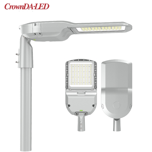
25W-320W FCC CE одобрил светодиодные уличные фонари серии S7 (B)
► Высокая эффективность: 130 лм/Вт, 150 лм/Вт и 170 лм/Вт.
► Антибликовый поликарбонатный объектив. Опциональный угол луча: 60°/90°/120°/T2M/T3M/T4M.
► 0–10 В с регулируемой яркостью / контроль времени / датчик освещенности / контроль лота
публикация